Learn how you can modify 3D print files in SOLIDWORKS
The world of 3D printing is rapidly expanding, making it increasingly important to be able to edit and customize 3D designs. There are communities, such as GrabCAD, dedicated to designers sharing their 3D printed models with one another and anyone else that’s interested. You can download the files for their designs and print it yourself (provided you have access to a 3D printer)!
While it’s extremely convenient to be able to download someone else’s 3D print file and create the part yourself, there may be slight modifications or adjustments you want to make to the design. If you’re provided with a solid modeling file like a SOLIDWORKS part file, then you’re in luck! With working CAD knowledge, you can simply tweak the features and modify the geometry to your needs. But what if you’re only given an STL file, which only includes graphical information? How would you go about making modifications?
The key here is finding a CAD software with the capability to convert graphical STL file information into CAD modeling data. There are a number of methods you could use (especially considering how many CAD software options exist today), but in this case I’ll be focusing on a solution in SOLIDWORKS.
How to bring 3D print files into SOLIDWORKS and convert them to solid bodies
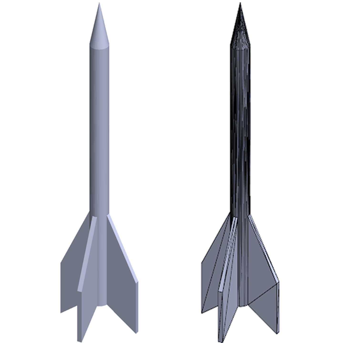
Let’s use this rocket design as an example. When importing into SOLIDWORKS, it’s brought in as a graphic feature that includes many triangular elements that make up the geometry.
Luckily, SOLIDWORKS allows you to convert these triangular elements into surfaces, which can then be converted into solid geometry. The “Surface from Mesh” command takes groups of triangular elements and converts them into one of four surface types: a planar face, a spherical face, a cylindrical face, or a conical face. You can convert the nose on the top into a single cone surface, the body of the rocket into a single cylindrical surface, and each of the fins into a few different planar faces. Now, this rocket is converted to surface geometry.
The easiest way to select numerous triangular faces, especially thin triangles like you see on this rocket, is to use the “Paint Select” option to click and drag over all the faces you want to include.
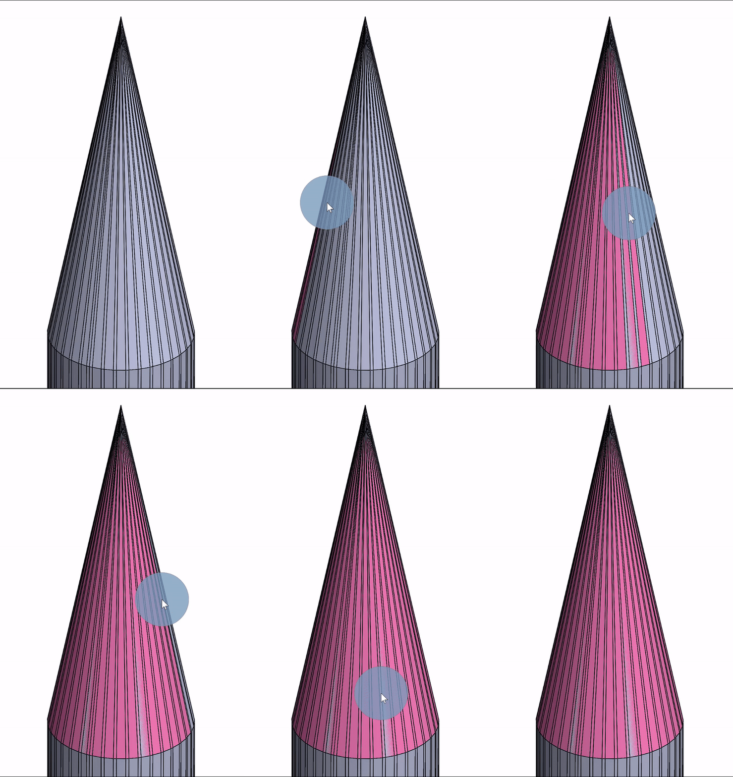
This allows you to quickly convert to surface geometry without needing to tediously select all the individual faces. If you’ve ever done that process before, you know how long it can take to select every one. Missing one of the faces when selecting can be very frustrating!
For this rocket, I have a total of 23 converted surfaces: one for the nose cone at the top, one for the cylindrical fuselage, five on each fin (20 total), and one more for the bottom circular face underneath the fuselage. Once all these surfaces are in place, I can use the “Knit Surfaces” command to knit them together and create a solid body.
Now, all the hard work of converting the triangular faces is done! From here, changes can be made to the model in much simpler fashion. For instance, you can decrease the number of finds on the rocket to three and shorten the overall height.
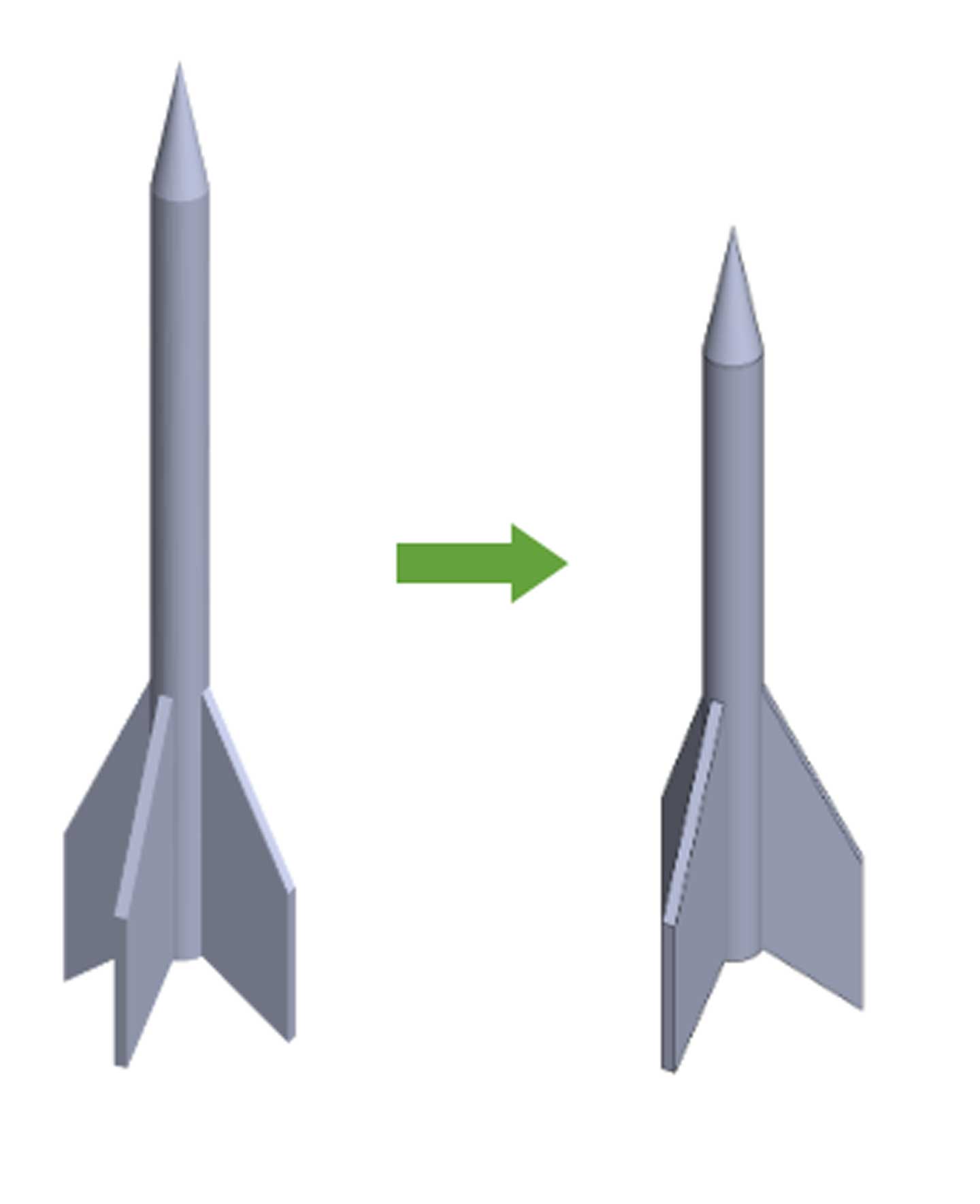
Of course, you can swap into CAD editing mode at this point, adding other features like a booster on the bottom, a viewing window on the fuselage, custom fin angles and tapering, or any other modifications you’d like. Once you’re over the hurdle of converting STL mesh geometry to a solid model, you can run at full speed!
There is one catch when converting STL files to solid bodies in SOLIDWORKS: the more complex the geometry on the 3D print file, the triangular elements you’ll have to convert to surfaces. You may also be required to do additional surfacing operations in the software before you can arrive at a solid body.
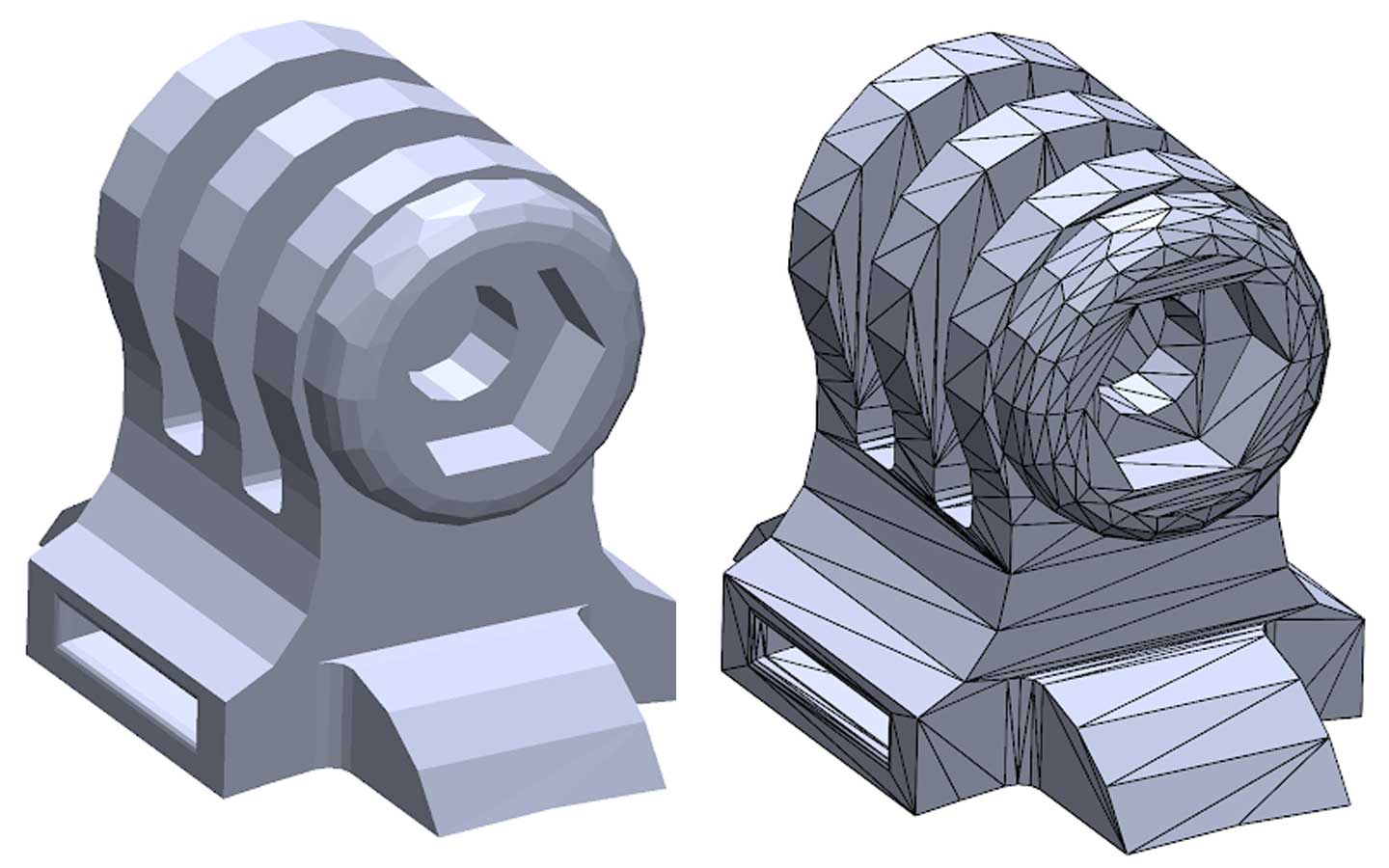
Take this GoPro camera mount, for example. The geometry isn’t particularly complex, but it has many more features and triangular faces than the rocket. There’s also a wider range of triangle sizes, from some that are easily visible to very narrow ones that are hard to see unless you zoom in. This makes it more time consuming and tedious to capture all the triangles and convert them to surface geometry.
Additionally, because the “Surface from Mesh” command focuses on converting to planar faces, spherical faces, cylindrical faces, and conical faces, it will be much more difficult to convert highly complex geometry to the types of surface geometry you’re looking for. In order to convert all the triangular faces into a solid body, you might have to use additional surfacing commands such as Trim Surface, Extend Surface, Ruled Surface, Boundary Surface, Filled Surface, and more. It’s important to consider these things when choosing a 3D print file, because highly complex models are going to require exponentially more time to convert.
There are always new 3D printing resources and communities springing up online. So, you can be sure to find a design you’ll want to modify and print yourself. The ability to make modifications to STL files for 3D printing is another handy tool you’ll have in your CAD skill set. Plus, if you’re sharing your own models, this can be a huge timesaver for others if you supply the original CAD design. That way, other users don’t have to go through the conversion process.
Keeping up with 3D printing advancements is an important part of being a great designer. Learn how to create functional and beautiful 3D printed parts and take your designs to the next level with SolidProfessor’s 3D printing courses!


