


Teaching (and learning) geometric dimensioning and tolerancing (GD&T) is no easy task. At first glance, some may assume that GD&T is simply a symbolic language with a list of definitions to memorize. It is more appropriate to consider GD&T to be a mindset supported by a symbolic language. It can take considerable time and effort to develop the GD&T mindset, as it forces us to acknowledge the full scope of characteristics that imperfect three-dimensional (3D) geometries can possess. With this article, we hope to make this task just a bit easier by addressing some common misconceptions that you may encounter as a learner, or instructor, tackling GD&T.
If you are an instructor with interest in these topics, please support an academic research study into the current state of dimensioning and tolerancing education by completing this survey (jointly conducted by researchers at Purdue University, UNC Charlotte, and Murray State University). Continue reading for more information!
Misconception #1: GD&T is only used for high precision applications.
Due to its apparent complexity, GD&T is often regarded as a tool of last resort for cases where the utmost mechanical and geometrical precision is required. Only here is the laborious and convoluted GD&T worth our while, supposedly. This is a misconception that downplays the power and robustness of GD&T as a specification tool and persuades learners to avoid the subject.
Debunking this misconception requires considering tolerances. Tight (small) tolerances are something we all know will drive up cost. One way to avoid unnecessarily tight tolerances is through the use of standard fits and tolerances such as those set out in American National Standards Institute (ANSI) B4.1 and B4.2 (these are commonly reproduced in references such as “Machinery’s Handbook.”) That said, these tables generally only help us tolerance relatively simple features with limit dimensioning (also known as plus/minus dimensioning), such as pins and holes. What are we to do when a more complex geometric characteristic, such as the position of hole, parallelism of two planes, or runout of a shaft requires tolerances? In cases where these geometrical characteristics appear to require tight control some designers might begrudgingly use GD&T. In cases where relatively loose tolerances might do, those who cling to Misconception #1 might say: “skip GD&T – the part doesn’t need it.”
This perspective misses a critical fact: There is nothing about GD&T that dictates that we must use it to create small tolerance zones. GD&T is just as utilitarian when used to specify large tolerance zones. Consider the drawing shown in Figure 1, which depicts a simple fixture or pillow block designed to hold a shaft or bearing in place. The size of the central bore must be precise, but it’s orientation to the faces of the block is clearly not of importance, nor is the flatness of those faces or the overall thickness of the block. This implies that the manufacturer does not have to machine the faces of the stock material – the only precision machining likely needed is a boring operation. Cost and time are thus saved by using GD&T to specify that low precision is explicitly acceptable!
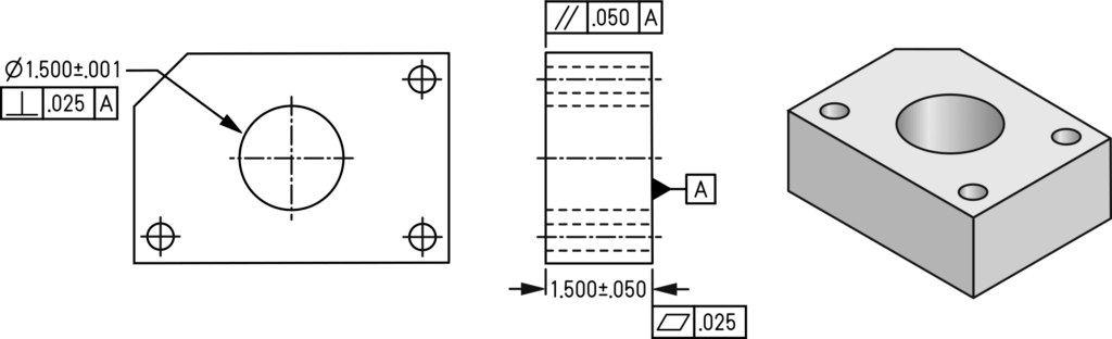
Figure 1. There are a variety of loose and tight tolerances on this drawing which clearly convey where precision manufacturing is required, and where it isn’t. Units are in inches. Note: This is not a complete engineering drawing.
Misconception #2: The print (designer) is always right.
As someone who has played the role of designer, machinist, and metrologist I’ve seen GD&T interpreted in a variety of ways. Generally speaking, the industrial standards we use to guide our interpretation and application of GD&T, such as American Society of Mechanical Engineers (ASME) Y14.5 or those issued by the International Organization for Standardization (ISO) Technical Committee 213, are quite mature. If our drawings are in accordance with a standard, the specifications should be able to be interpreted unambiguously by all involved. The weak point here is not lack of clarity in the standards, it’s the humans.
There are two underlying forces behind Misconception #2 that we should address. First, the computer-aided design (CAD) software programs that engineers, technicians, and draftspersons (all referred to herein as designers) use when applying GD&T to drawings are dumb. That is to say, there is very little intelligence built into these software tools to prevent designers from misusing and abusing GD&T in nonsensical ways. You will likely not be warned that you applied a datum to a tolerance of form (which should have no datum reference), you’ll be allowed to invoke datum reference frames that constrain unintended degrees of freedom, and you’ll be able to apply feature control frame leaders to construction lines and center lines that shouldn’t have them. Simply put, CAD is dumb and it’s up to the designer to be smart.
Unfortunately, designers are not always smart – we get it wrong sometimes. Just like writing the first draft of an essay that is clunky and full of grammatical errors, the first draft of a drawing is not likely to be clear or without mistakes. This is the very reason why large companies use product lifecycle management (PLM) tools to formally involve senior or expert personnel who can play the role of drawing checker. This is also why the designer should make a habit of walking over to the shop floor or quality department with a draft print in hand. Stakeholders in the lifecycle of a product, especially those such as machinists or metrologists who have to meet specifications on the print or verify against them, will have valuable insight and feedback to give.
Misconception #3: Datum precedence does not matter.
Datums… the often-misunderstood foundation of the house of GD&T. There are enough misconceptions about datums to fill up an entire series of articles! Here, we will only discuss one especially prevalent misconception: Datum precedence does not matter.
To review: a datum is a theoretically exact geometrical element derived from the true geometric counterpart of a datum feature. For example, if a nominally flat face is called out as a datum feature on a drawing, the datum is the perfectly flat theoretical plane associated with the imperfect feature on the physical part.
Datums are used to establish references for specifying and measuring location and orientation. This is done by placing datums in the feature control frame (see Figure 2). In this drawing, the feature control frame specifies that the position of the central bore must lie in a cylindrical tolerance zone .005 inches in diameter basically positioned (at its nominal position) in the -ABC- datum reference frame (DRF), a sort of virtual coordinate system.
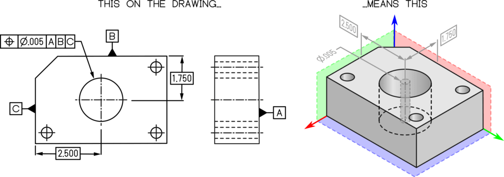
Figure 2. This drawing specifies that the position of the axis of the central bore must lie in a .005 diameter tolerance zone basically located in the -ABC- datum reference frame. Units are in inches. Note: This is not a complete engineering drawing.
As it turns out, the order of the datum symbols in the feature control frame matters. This is known as datum precedence. The first datum is known as the primary datum, the second as the secondary datum, and the third as the tertiary datum. You do not need to have three datums in a datum reference frame and they do not have to constrain all six degrees of freedom (two more misconceptions for another time). Datum precedence can have drastic impacts on how a part is manufactured and inspected. For example, Figure 3 shows the -ABC- and -ACB- datum reference frames. Since it is impossible to generate perfect geometry, such as two perfectly flat and perpendicular surfaces, one datum feature must take precedence over the other. The result is that the bore in question takes on a different position within the datum reference frame. Although this topic is too large in scope to fully cover in this article, datum features and datum precedence should be selected by the designer to mimic the functionality of the workpiece.
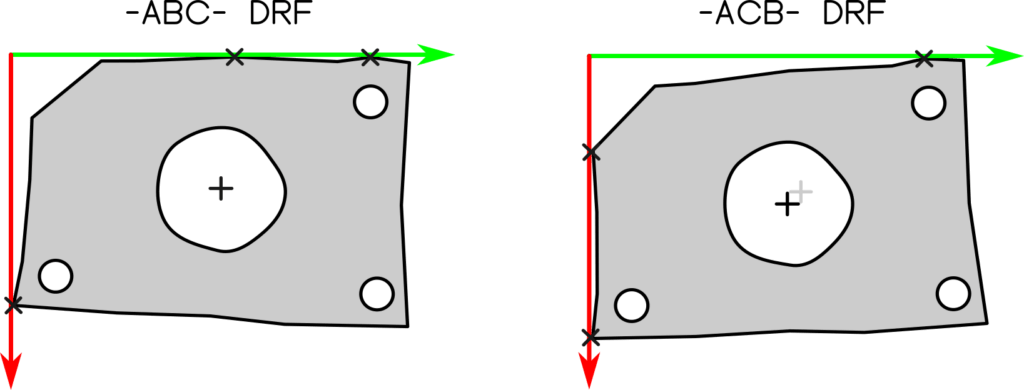
Figure 3. Notice how, in the -ABC- DRF, datum -B- contacts the coordinate system at two points and datum -C- at one point. This is reversed in the -ACB- DRF. This results in the position of the central bore moving within the DRF as visualized via the black and gray center lines showing the new and old positions.
In summary
Along your GD&T journey you will likely encounter other misconceptions, innocently or intentionally passed along by word of mouth or even in print. Remember to always reference back to the technical standards, speak to the skilled practitioners around you, and approach every drawing ready to correct old habits and build new ones. And don’t forget – the best way to learn GD&T is to use it!
Copyright © J. Berez, 2024
Are you interested in the current state of GD&T in college classrooms? Are you faculty or staff that teaches engineering graphics, CAD, CAM, MBD, standards, or quality control? We want to hear from you! We are a multi-institution team conducting a research study to assess who teaches dimensioning and tolerancing, how they teach it, what resources they use, what challenges you face. Access the survey HERE
Jaime Berez, Ph.D., Asst. Professor
Center for Precision Metrology, UNC Charlotte
Rustin Webster, Ph.D., Assoc. Professor
School of Engineering Technology, Purdue University
Rudy Ottway, Ph.D., Assoc. Professor
School of Engineering, Murray State University